Wednesday, December 19, 2012

Install Windows 2008 R2 NPS for RADIUS Authentication for Cisco Router Logins


 In this example I will install the Network Policy Server to support RADIUS on a Windows 2008 R2 domain controller and give router login access to an Active Directory domain user.

First go into Server Manager.


Highlight Roles on the left side, then in the Role Summary section click Add Roles on the far right.


When you reach the Select Server Roles screen, check Network Policy and Access Services.  Click
Next.


Check Network Policy Server only, then click Next.  Then click Install and and confirm the install was successful.
Now go to Start > Admin Tools > Network Policy Server.


In the left pane open up Policies, then right click Network Policies and select New from the menu.


Type a name for the new login policy, leave the network access server type at Unspecified and click Next.


Click Add to add the conditions necessary for this network policy to be run.


We will specify that this policy is run for users in a specific Windows group, so highlight Windows Group and click Add.


Click Add Groups.


Type the name of the user group that you want to grant Cisco login access to.  I will give this access to my Domain Admins.  Click Check Names to verify, then click OK.


Click OK.


Optionally we can specify that this network policy will apply to a specific RADIUS client (i.e. Cisco router).  click Add.


Select Client Friendly Name, click Add.


Type a friendly name for your router.  As it says you can use pattern matching such as a wildcard (*) if desired for this to apply to multiple devices.  Click OK.


Now we click Next.


If the policy conditions are matched we want to provide access so select “Access granted” and click Next.


The Cisco IOS requires unencrypted authentication methods so select “Unencrypted authentication (PAP, SPAP)”.  Click Next.


We get a warning about selecting the unencrypted authentication type, click No unless you want to do some reading.


We can set additional constraints to match for the policy to apply.  Just click Next.


This policy will apply to router logins only so we’ll specify an attribute to identify this connection type.  Highlight Standard under RADIUS Attributes and in the right side and delete both attributes that are already there.  Then click Add.


With Access type set to All select the Service-Type attribute, then click Add.


Under Attribute Value select Others, then select Login from the menu.  Click OK.


Click Close.


This next attribute setting is optional but often configured to allow users to automatically have their privileges elevated to privileged (15) EXEC mode when they login to the Cisco router.  Under RADIUS Attributes select Vendor Specific.  Click Add.


With Vendor set to “All”, select Vendor-Specific for the attribute and click Add.


Click Add.


For the attribute information select “Select from list” and choose Cisco from the menu.  Then select “Yes. It conforms” and click Configure Attribute.


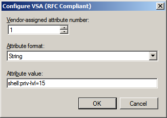
For the Vendor-assigned attribute number enter 1, for Attribute format choose String, and in Attribute value type:
shell:priv-lvl=15
Then click OK.


Click OK.


Click Close.


Click Next.


Finally click Finish.


Now we need to specify the Cisco router as a RADIUS client to the Windows NPS server.  Back at the Network Policy Server console in the left open up RADIUS Clients and Servers, then right click RADIUS Clients and choose New from the menu


In the New RADIUS Client dialog type the friendly name that you specified earlier in the network policy for this router.  Enter the IP address for the device, use the IP of the router interface closest to the Windows server or use the IP of the interface that you specified if you used the “ip radius” command when configuring the Cisco device.  Finally enter the shared secret RADIUS key that you specified over on the router.  Now click OK.


Now the NPS service needs to be activated in Active Directory.  Right click the NPS tree root on the left pane, and choose “Register server in Active Directory”.


Click OK.


Click OK again.

Finally I have noticed that NPS doesn’t seem to work after all this configuration until I’ve restarted the service.  So once again on the NPS tree root right click it and select “Stop NPS Service”.  It seems to take a few moments for the service to actually stop so wait 10-15 seconds then right click NPS again and choose “Start NPS Service”.  Switch over to your router and make an attempt to login.
One thing to keep in mind with these Network Policies in NPS is that some of their settings can be overridden by Connection Request Policies.  Daryl Hunter noted this in his blog on the subject, so keep this in mind of you have any difficulties.  Hope all goes well!

References

RADIUS Authentication for Cisco Router Logins

RADIUS or Remote Authentication Dial In User Service is a protocol that allows us to centralize the authentication and authorization of systems to connect to network resources.  In this example I will configure a Cisco router to use RADIUS to authenticate users for logins to the Cisco command console.  This will ease the administrative burden from needing to set up multiple local user databases on each of our routers.
First let’s make sure that the new AAA command set is active:

R1# conf t
R1(config)# aaa new-model
 
If you don’t already have a user configured in the local user database on the router it is a good idea to create one.  This is important so that you can access you router remotely in the event the RADIUS server becomes unavailable to the router.  We also need to make sure that we have an enable password set for privileged EXEC mode.  I will use the secret modifier on both so that the passwords are encrypted with the stronger type 5 MD5 hash table:
 
R1(config)# username john secret JohnsPassword
R1(config)# enable secret EnablePassword
 
Now we’ll specify the IP address of the system that will be our RADIUS server.  We can include an encryption key unique to each RADIUS server or we can specify a key globally.  I’ll use a global key.  Also optionally we can specify the ports used for RADIUS authentication and accounting, these default to 1645 and 1646 but I’ll specify them in the command anyway.

R1(config)# radius-server host 192.168.2.5 auth-port 1645 acct-port 1646
R1(config)# radius-server key MyRadiusKey
 
To encrypt the RADIUS key we’ve entered enable the password encryption service.  This enables relatively insecure type 7 encryption on the key, but it’s better than leaving it there in plain text!

R1(config)# service password-encryption
 
We’ll activate authentication for logins to the router and specify that RADIUS is the preferred method but we’ll include the local user database as a fall back if RADIUS becomes unavailable.  Note that users in the local database cannot be used if the user doesn’t exist in RADIUS, it will only fall back if the RADIUS server is offline.

R1(config)# aaa authentication login default group radius local
 
This command is optional but will automatically take RADIUS authenticated users to privileged Exec (15) mode without requiring them to type “enable”.

R1(config)# aaa authorization exec default group radius if-authenticated
 
Specify the interface with the source address supplied in RADIUS traffic.  In my case I have a router with a VLAN interface configured, otherwise you can use a physical interface.

R1(config)# ip radius source-interface Vlan 10
 
Now it is time to set up our RADIUS server to allow the Cisco router to use it’s authentication services.  In my example I will make use of a Windows RADIUS server in an Active Directory domain.  Below you can find an article on configuring RADIUS services on a Windows Server 2003 domain controller.

References
http://www.blindhog.net/cisco-aaa-login-authentication-with-radius-ms-ias/

Integrated Routing and Bridging (IRB) On 888 Cisco Routers

I used this feature to bridge local interface to ATM as fallowing consideration:

Using the integrated routing and bridging (IRB) feature, you can route a given protocol between routed interfaces and bridge groups within a single switch router.


Because bridging is in the data-link layer (Layer 2) and routing is in the network layer (Layer 3), they
have different protocol configuration models. With IP, for example, bridge group interfaces belong to
the same network and have a collective IP network address. In contrast, each routed interface represents a distinct network and has its own IP network address. Integrated routing and bridging uses the concept of a Bridge-Group Virtual Interface (BVI) to enable these interfaces to exchange packets for a given protocol.

A BVI is a virtual interface within the campus switch router that acts like a normal routed interface. A BVI does not support bridging, but it actually represents the corresponding bridge group to routed
interfaces within the switch router. The interface number is the link between the BVI and the bridge
group.
Layer 3 switching software supports the routing of IP and IPX between routed interfaces and bridged
interfaces in the same router, in both fast-switching and process-switching paths.

Before Configuring IRB

Consider the following before configuring IRB:
• The default route/bridge behavior in a bridge group (when IRB is enabled) is to bridge all packets.
Make sure you explicitly configure routing on the BVI for protocols that you want routed.
• Packets of nonroutable protocols such as local-area transport (LAT) are always bridged. You cannot
disable bridging for the nonroutable traffic.
• The protocol attributes should not be configured on the bridged interfaces when using IRB to bridge
and route a given protocol. Bridging attributes cannot be configured on the BVI.
• A bridge links several network segments into one large, flat network. To bridge a packet coming
from a routed interface among the bridged interfaces, the whole bridge group should be represented
by one interface.
• The BVI has default data-link and network-layer encapsulations. These encapsulations are the same
as on the Ethernet, except that you can configure the BVI with some encapsulations that are not
supported on a normal Ethernet interface.

Configuring IRB

To enable and configure IRB and BVI, perform the following steps, beginning in global configuration
mode:

 To verify the IRB configuration, use the following commands:

show interfaces bvi interface-name
show interfaces irb 

Hesre Is Sample Configuration :

version 15.0
no service pad
service timestamps debug datetime msec
service timestamps log datetime msec
no service password-encryption
!
hostname *****
!
boot-start-marker
boot-end-marker
!
!
no aaa new-model
memory-size iomem 10
!
!
ip source-route
!
!
ip dhcp excluded-address xxxxxxxx xxxxxxx
!
ip dhcp pool lan
   network xxxxxxx xxxxxxx
   default-router xxxxxxx
   dns-server xxxxxxx
   lease 30
!
!
ip cef
no ipv6 cef
!
!
!
username xxxxxxx privilege 15 secret 5 xxxxxxx
!
!
controller DSL 0
 mode atm
 dsl-mode shdsl symmetric annex B
!
!
!
!
bridge irb
!
!
!
!
interface BRI0
 no ip address
 encapsulation hdlc
 shutdown
 isdn termination multidrop
!
interface ATM0
 no ip address
 no atm ilmi-keepalive
 bridge-group 1
 pvc 0/55
  encapsulation aal5snap
 !
!
interface FastEthernet0
!
interface FastEthernet1
!
interface FastEthernet2
!
interface FastEthernet3
!
interface Vlan1
 ip address xxxxxxx xxxxxxx
!
interface BVI1
 ip address xxxxxxx xxxxxxx

!
ip forward-protocol nd
no ip http server
no ip http secure-server
!
ip route 0.0.0.0 0.0.0.0 xxxxxxx
ip route xxxxxxx 255.240.0.0 xxxxxxx
!
!
!
!
control-plane
!
bridge 1 protocol ieee
bridge 1 route ip
!
line con 0
 logging synchronous
 login local
 no modem enable
line aux 0
line vty 0 4
 logging synchronous
 login local
!
scheduler max-task-time 5000
end

Sunday, December 16, 2012

MikroTik Bandwith Management

There are two ways how to make this: using mangle and queue trees, or, using simple queues.

1. Mark all packets with packet-mark all:

/ip firewall mangle add chain=prerouting action=mark-packet new-packet-mark=all passthrough=no

2. Setup two PCQ queue types - one for download and one for upload. dst-address is classifier for user's download traffic, src-address for upload traffic:

/queue type add name="PCQ_download" kind=pcq pcq-rate=64000 pcq-classifier=dst-address
/queue type add name="PCQ_upload" kind=pcq pcq-rate=32000 pcq-classifier=src-address

3. Finally, two queue rules are required, one for download and one for upload:
/queue tree add parent=global-in queue=PCQ_download packet-mark=all
/queue tree add parent=global-out queue=PCQ_upload packet-mark=all

Vlan On MikroTik RouterOS

This exam learn how to create VLAN on MikroTik RouterOS

[admin@MikroTik] interface vlan> add name=test vlan-id=32 interface=ether1
[admin@MikroTik] interface vlan> print
Flags: X - disabled, R - running
#   NAME   MTU     ARP       VLAN-ID  INTERFACE
0 R test   1500    enabled   32       ether1
[admin@MikroTik] interface vlan>


that's easy

Integrate Active Directory with Mikrotik

AAA with Active Directory

 MT setup

 /ip radius add
   service=ppp,wireless
   address=<ip address of AD server>
   secret=<password for RADIUS service on AD server>
   authentication_port=1812
   accounting_port=1813
 /ip ppp AAA
   use_radius=yes
   accounting=yes
 /ip ppp pptp-server
   enabled=yes
   authentication=mschap1,mschap2
Windows Setup
 Start->Control Panel-Administrative Tools->Internet Authentication Service
 Right-click on RADIUS Clients->New
 Friendly Name: MikroTik
 Address: <ip address of MT>
 Client-Vendor: RADIUS Standard
 Shared secret: <password used to access the RADIUS service>

 Reference Link Here....